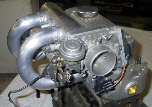
| Here's my first shot at the
project. The manifold is 14 ga aluminium hammer formed, in halves, over an oak
buck, then butt welded together. I
aimed the throttle body over the rockerbox where I was going to make a plenum
that lead to the air filter somewhere down in front, maybe even ram air? The air plenum is 1/4" plate. It never
got finished because when I got to this point I realized there wasn't enough
room for the fuel rail! I could make something that would work, but there
wasn't really enough room to get it in and out to change injectors. Sigh, into
the scrap bin and start again. |
|
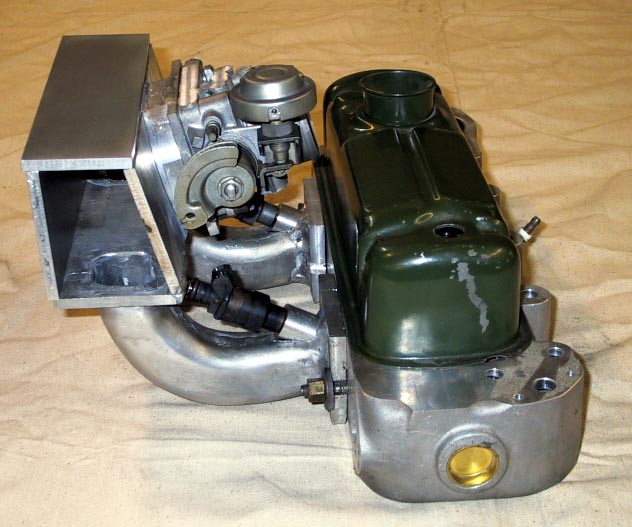
| Here's the second attempt. A '95 Ford Escort
donated the cast aluminium plenum and 180 degree 'bananas'. I started by
cutting off the 4 bananas, the flanges on the head and the flange for the
throttle body. The Ford uses a tiny 32 mm throttle body which I left in
the junk yard. No wonder those things are so SLOW! |
 |
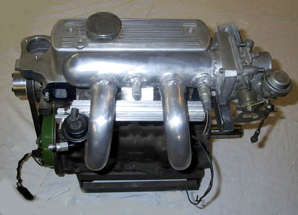
| Once I had a pile of useful parts I made the
flange for the head. With the plenum, throttle body and fuel rail all hanging
off the flange, I figured I would extend the plate against the head up high
enough that I could pickup the plenum. The extension for the ports is drawn
heavy wall aluminium tube, the injector bosses are made from bar stock as is
the fuel rail.
The fuel pressure regulator is a Bosch OEM piece used on GM
3.0 V6 and operates at 3 Bar.
Injectors are laid back as far as I could. They aim at the
port floor just upstream of the port divide.
|
 |
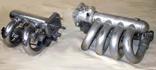
| With the head side of the manifold mocked up I
cleaned up the plenum so the original bananas fit back in where they came
from. Interestingly, Ford 'soldered' the manifold together. The material
holding the formed bananas to the cast plenum and flanges is an alloy with
slightly lower melting temperature. It's all easy enough to machine, but when
it comes to TIG welding there's a lot of junk in there! |
 |
|
I used 2 holes in the plenum to feed the head,
one for the manifold air temperature (MAT) sensor (Delphi) and the last for a
vacuum take off to feed the fuel pressure regulator and manifold absolute
pressure (MAP) sensor (Delphi too).
The 55 mm throttle body is from a Mazda 626. There's a
50 mm
body of identical design, from a Mazda 323, just in case the larger one
doesn't deliver enough throttle sensitivity down at the bottom end.
A Ford V8 donated the throttle position sensor.
|
 |
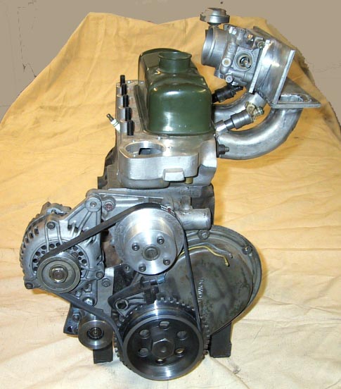
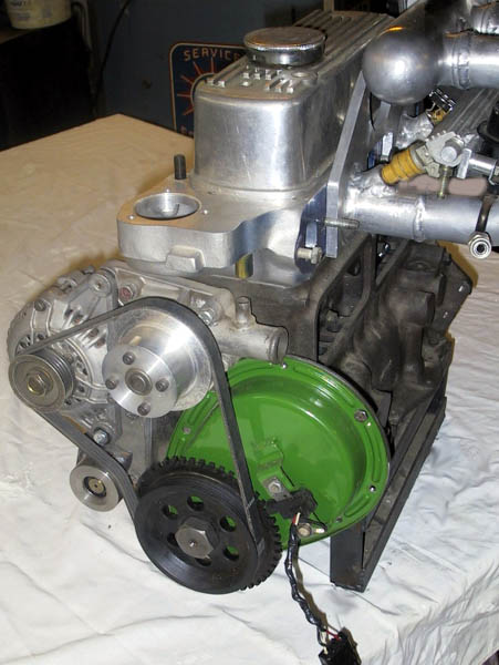
On this end of the engine is
 | a home brewed 48 tooth timing wheel with 4K spline
belt drive |
| Rennex (Renault Alliance) variable reluctance sensor
for crank position sensing |
| 4K spline belt water pump pulley - from aluminium bar
stock |
| Nippon Denso (Toyota) 75 amp alternator hard mounted to block |
| idler pulley made from 4130 bar stock (it's what I have
in the scrap bin!) |
|
 |
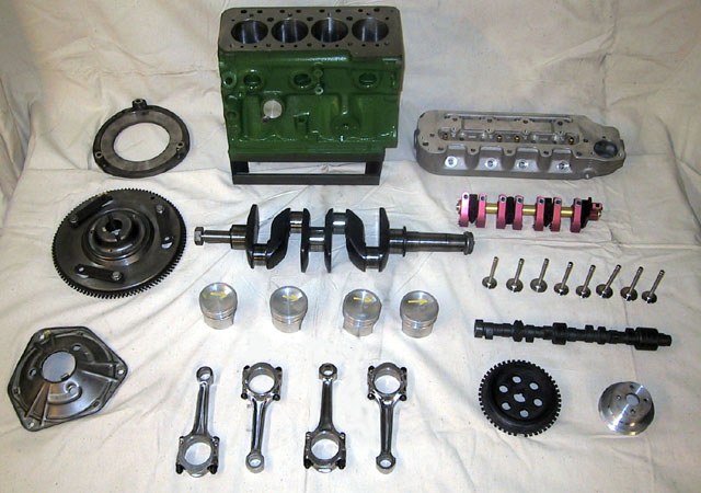
Here's the engine :
| lightened steel flywheel and backing plate with blue (80
ft-lb) spring |
| wedged, polished and nitrided crank |
| +0.020 Hepolite 21251 pistons |
| Lightened and polished rods |
| Pierce aluMINIum head |
| Minisport 1.5:1 roller rockers |
| Kent 266 cam |
| home brew 4K spline pulleys for water pump and crank
(with timing teeth) |
|
 |
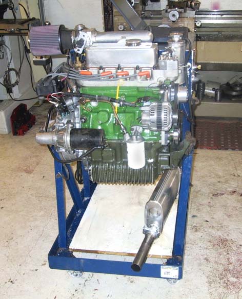
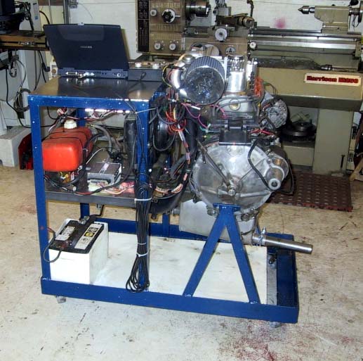
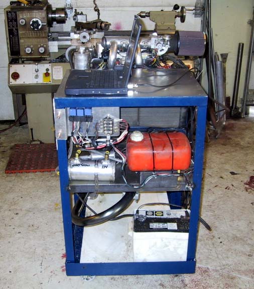
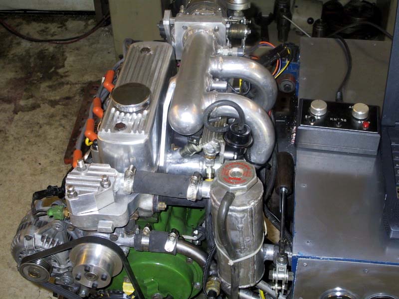
Four views of the engine installed in the test
stand. Clockwise from left top:
| Engine side - the clean look |
| My control side - Laptop jacked into ECU, dyno control on
the left, analogue instruments on the apron. The rad swirl pot drain is
aimed right at my foot! |
| The system side - on the shelf is the 5 l fuel tank, a 1
l surge tank, low and high pressure pumps and filter. Immediately behind
the engine is the rad and electric fans |
| The clutch side - battery tucked into a corner away from
the exhaust. The ECU sits beside the tank. On top of the clutch
housing is the coil pack. |
|
    |
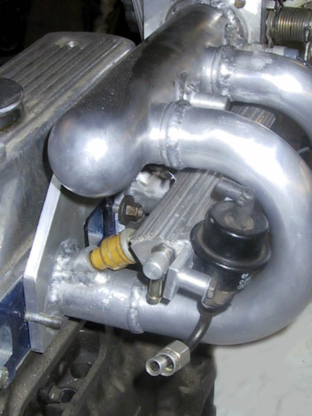
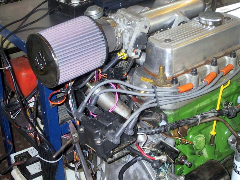
| A couple of quick detail views showing the
location of the coil pack (left) and where ALL the action is (right). It's all
about aluMINIum ain't it? Almost everything in this picture was made in the
last couple of months in my workshop. What you can't see is the two oxygen
sensors in the LCB branches. One for outside cylinders and one for inside.
|
|
Hear
it run! Yes, it does did run, but with all the challenges presented by the
siamese port head, it only runs ran well within a small rev range. This sound clip
was done with 200 cc/min injectors so it runs well at idle up to 3000 RPM
after which it drops the outside cylinders. The 500 cc/min injectors can run up to
5000 RPM, but it wouldn't idle because the pulse width got down to the
reaction time limit of 2.5 ms.
First off let me say that the DTA ECU is fantastic. It’s
easy to use, does just what it is designed to and does it very well. If you
are planning on injecting an engine other than one with a siamese port head, I
would strongly recommend a DTA. If you are expecting plug-and-play you’ll be
disappointed but perseverance will pay off. On the downside, their manual and
help files are written by a techie who assumes you know how everything is
supposed to work so if you have a problem it’s entirely up to you to figure
it out. The Email support I got from DTA in England wasn’t terrific, OK if
truth be told, it was always curt, not very helpful and occasionally rude. Which is better than
the response I got from their Canadian agent who seemed completely
disinterested in dealing with customers. That is, when he bothered to answer
the phone at all.
DTA market their system as being applicable to BMC A series
engines. They took an extremely simplistic approach to the problems presented
by the siamese port head, stating that all that’s required is "run it in
2-stroke mode and Bob’s yer uncle". If the siamese cylinder cycles were
360 crank
degrees apart that would work just fine, but, unfortunately for us, they are
only 180 degrees apart and draw through the port asymmetrically. DTA have
never
set up an A series engine and do not know anyone who has, so
claiming it would work was a bit of a stretch. Between April and June 2002 I spent an
unreasonable amount of time conducting tests to search out the operating
envelope for this engine, continually updating DTA on my progress.
Unfortunately they didn’t take too much of an interest in my work and
offered few suggestions on how to resolve problems. It was clear that they did
not understand the problem, or just didn’t care enough to think about the data I was sending them.
Pitty.
Without fundamental changes to the DTA ECU it will not work
for siamese port engines. Since DTA were unwilling to make the
modifications I suggested, they offered to take their system back for
a full refund.
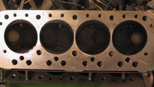
This photo probably tells the story best. The last time the
engine ran it was with injectors too big to work at idle, so it's showing a
lot of soot, but the #1 & 4 exhaust valves were running much hotter than
#2 & 3. This just confirms what I was seeing on the O2 sensors: it wasn't
running balanced.
|
|
This project is now being reworked as an 8-port EFI. The 5-port
manifold is on the shelf in hopes that someday one of the ECU manufacturers
will follow up on my research and actually rework their software to make it
work. DTA can't be bothered and although Emerald showed quite a bit of
enthusiasm, they have since stopped replying to Email. Curious.
As of February 2003 I am working on the inlet manifold for
the Elder 8-port. I'll completely redo this page when I have that done and I'm
a bit closer to getting the thing running again. Yes, it will be using the DTA
ECU. When you come right down to it, it's a very good unit and it will work
just fine on the conventional head.
I'm also exploring the possibility of using a Land and Sea
dyno on my test stand. These things are quite reasonably priced and
although I only really need a load to rough in the fuel and ignition map, they
can supply a load cell and readout so I can log torque and integrate BHP.
Gotta raise some real live US Greenback currency though. Watch for stuff on
Ebay!
|
| Linques!
|