EFI 8-Port Project
This is a quick-and-dirty place holder page for this project. I'll do a
better one when I have time |
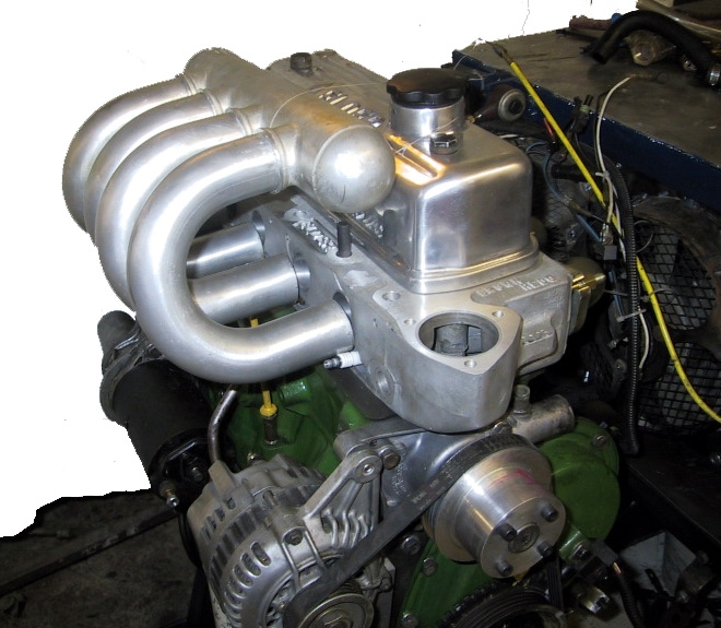 |
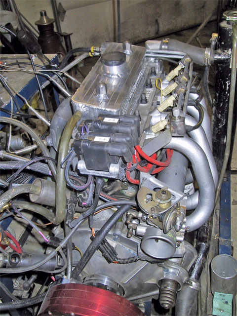
This is the original concept for the inlet manifold. The
starting point was a manifold from a mid-90's Ford Escort. Unfortunately
this did not leave clearance for the bonnet, so a decision was made to
move the plenum down parallel to the block. Since full engine
management will be used, there is no distributor to interfere. |
 |
Flanges were made from 1"x3" bar stock, then the manifold
started with 1.125" U-bend tubing. |
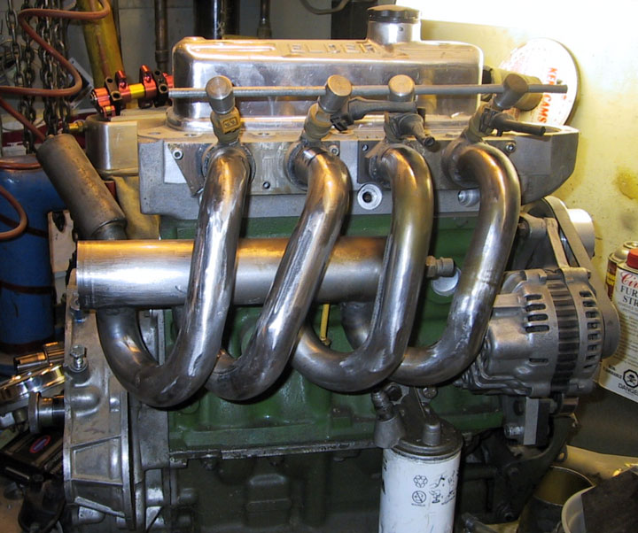 |
The plenum is sheet steel, rolled into a log with belled ports in the
floor. Because the ports are splayed and angled up from the block the fuel
rail was a bit of a challenge. Injector bosses were made from bar stock,
drilled on an angle then lined up on 5/16" ridged tubing before they
were silver soldered in place. |
|
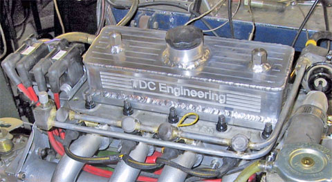
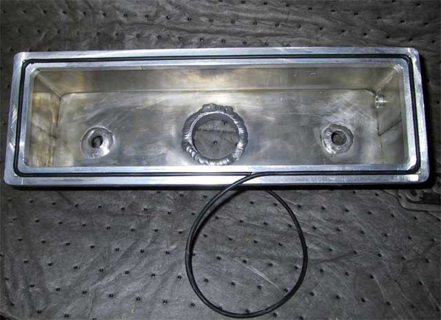
The rocker cover supplied by Elder is not very refined and it needed a
considerable amount of grinding to clear the 1.5:1 rockers. I thought it
would be less work if I just made my own. Of course, I was wrong, but the
end result is nice!
Instead of dealing with those horrible cork gaskets, a 1/8" groove
was cut in the base flange so an O-ring could be inserted. It's cheap,
won't move around and absolutely will not leak. Why don't they all do it
this way? |
 |
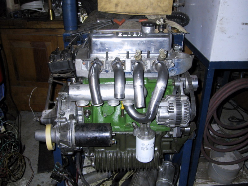
The manifold is designed with 18" of runner length, which my
calculations say will resonate at around 3000 RPM to give a nice flat
torque curve. The runners will clear the grille of a round nose Mini.
The throttle body is 50 mm Mazda, the coil pack is from Hyundai and the
injectors are Bosch 220 cc/min. |
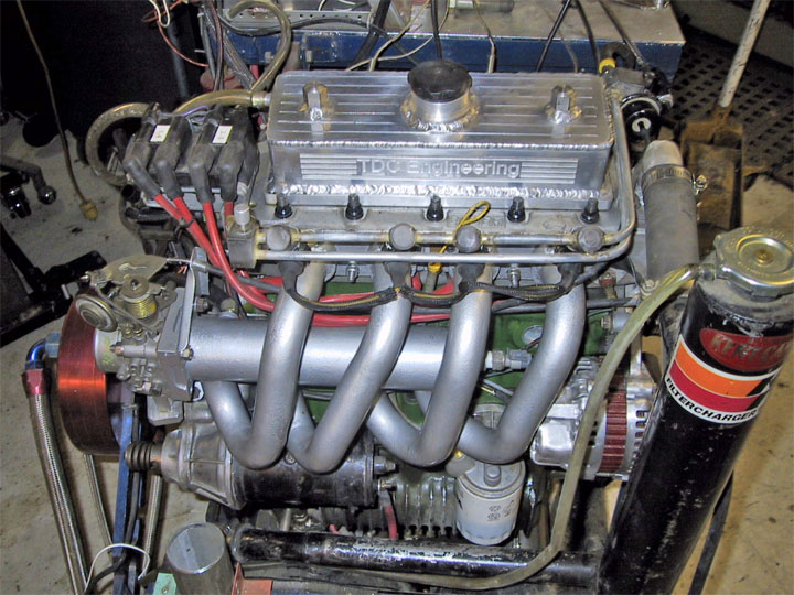 |
Here's the finished product. You can hear it running here
Yes, that is a waterbrake dynamometer hanging off the clutch end. Time
did not permit acquisition of any meaningful power data, but 2007 is
another year. |
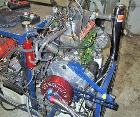 |
This is an older photograph of the 200 Hp Land and Sea snowmobile dyno.
Updates have been the addition of a data acquisition system that records
EGT on all 4 branches, two channels of O2, crank position, RPM, system
temperature and, of course, torque. The DYNOmite torque arm with it's
single bridge strain gauge has been replaced by a full bridge strain gauge |
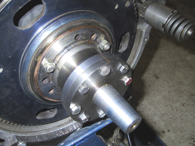 |
Before you Email me to ask how the dyno is driven, here's the adaptor to
get from a Mini crank taper to the snowmobile taper. All these parts were
fabricated in the garage workshop. |
|
|
|
|
|
|
|
|
|
|
|
|
|
|
|
|
|
|
|
|
|
|